Hiya Craig.
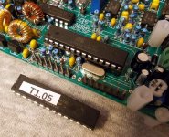
The cases look OK. I thought it was screen printed when I first saw one, but when my purchase arrived and I had a closer look I could see that it is a printed vinyl wrap, so we need to make sure it doesn't get any hard knocks else it may rip or scuff.
I performed the firmware update with the chip out of the board. The programmer I used is one I bought for use at work, so because it was to hand it was my first choice. I think it is possible to use a USBASP programmer, or anything else that can program Atmels via the six pin header on the PCB. I do have some USBASP programmers, they only cost pennies to buy, which I purchased to reflash the bootloader in an Arduino I had killed by writing to the wrong area of memory.
I might have a go at updating the firmware of a chip using one of the USBASP leads, just to see how 'easy' it is. I also have a dedicated AVR programming interface made by Mikroelektronika, which I use with their AVR IDE.
Anyway, the programmer I used was a cheap Chinese made USB 'universal programmer', and this was controlled by the free software provided by the manufacturer. Using that it is possible to extract the Code memory information, the Data memory information, and the Config data.
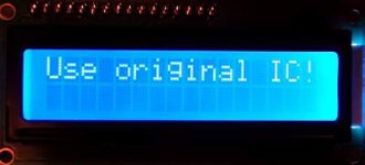
Starting with a blank AVR (Atmega 328P-PU in my case, the original is a 328P-U, any 328P will do), you need all three sets of data to get the thing to work. So if say you had a blank chip and just programmed in the new firmware, it would do nothing. Apart from the 'code', if you then set the fuses/config info too you would start to see some life, but in the case of these radios you get a warning/error message that says, "Use Original IC!".
So you must have the Code, Data, and Config info all programmed in to get the item to work. After having a look at the firmware update file it seems that what is in there is just the Code for the IC, it is not a complete all in one package. After a little bit of experimentation (and after making sure I could successfully recreate working clones of the chips for the rig), I adopted the following route.
1) I erased the new Atmega 328P-PU IC
2) I opened up the firmware file (which was in hex format), this becomes loaded in to the programmers IDE buffer
3) I read the Data and Config info from the original IC
By this point I now had New-Code/Data/Config in the buffer. It was just a case of hitting the program button and it was done, a cloned Atmega IC loaded with the new firmware plus the data/config info from the original IC.
After the new IC was tested in the radio, I then removed it and read/saved the entire 'project' so that if I need to replace the IC at any point I can just open the file and send it to another new Atmel rther than having to mess around opening files and reading the old IC to get everything I need.
Like I said earlier, I haven't tried the on-board header method yet, but I will just to see what can be done with via that technique. The way I did things here seems to have worked fine, but when we get to the latest QCX-mini boards I'm not sure if you can remove the Atmel, or if it is surface mounted and pre-fitted on the PCB. If it is 'fixed' within the rig then the header method would be the only means available so it would be worth mastering the system just for that.
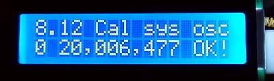
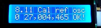
After I updated the firmware any calibration data would be the default set, so I next wired up the GPS board and calibrated the on-board references. Before calibration I had tuned around on air and it was quite noticeable that stations seemed to be operating on odd offsets and seemingly strange frequency steps. Once the calibration was done however it was a different world when tuning around! Everything made sense, stations heard were where you would expect to find them and so on. So calibration is well worth doing, if not indeed a must!
It is possible to calibrate the QCX without using the GPS module, but it is so much easier and quicker with that unit, it really is.
Some things I have found 'odd' with the QCX are:-
1) No on-off switch :-*
2) No AGC :-*
3) Both the S-meter and the Decoder are connected AFTER the volume control :-*
4) The headphone socket is configured such that if you use a mono connecting plug it shorts out the audio :-*
5) The audio filter is said to be 200Hz BW, yet it sounds much wider in use :-X
6) No RF pre-amp on receive, incoming signals go directly in to the sampling detector :-*
The most annoying one of all of he above is the lack of AGC. While listening to a contest this weekend I was forever having to turn the volume up and down, and very often when listening to a weak station I was deafened by much stronger stations replying. Listening around again tonight there was some deep rapid QSB present on some signals, and the changes in audio level were really noticeable and very annoying.
Mind you, this is not the only QRP rig with 'quirks'. I have an LNR MTR-3 mountain topper rig, that one does have AGC but no volume control! What!
Anyway I've rambled on enough for now :-[
73, Mark...

 .
.